

1. Introduction
2. Testing Materials and Methods
2.1 Gyeongju Bentonite
2.2 Preparation of Compacted Bentonite
2.3 Testing Setup and Equipment
3. Experimental Results and Discussion
3.1 Compressive Wave Velocity
3.2 Young’s Modulus Emax and Constrained Modulus Mmax
3.3 Material Damping Ratio Dmin
3.4 Poisson’s Ratio
4. Conclusions
1. Introduction
Clay minerals composed of bentonite is identified as a suitable candidate for buffer materials, where bentonite is a part of the smectite group containing large amounts of montmorillonite, having a self-sealing property which is advantageous for the repository assembly phase. Compacted clays are used as insulating barriers in geotechnical and geo-environmental applications (Koch, 2002). In particular, Gyeongju bentonite is a compacted buffer material commonly produced in Korea. This highly compacted buffer material plays an important role as a part of an engineered barrier system (EBS), acts as a sealing liners of radioactive waste repository, which guarantees safe disposal of high-level waste (HLW) and protects the canister against any external mechanical impact. Moreover an EBS is composed of a disposal canister with spent fuel, a buffer material, backfill material, and a near field rock mass at depths of 500 to 1,000 m below the ground surface (Fig. 1). It also serves as a gap filling material that secures the canister in place, minimize inflow of groundwater and protection against shear behavior of neighboring rock on the deep geological repository site. Especially, the compacted bentonite buffer material undergoes swelling stress by groundwater penetration and thermal stress by decay heat from canister. In order to design the compacted bentonite endurable to these swelling and thermal stresses, the mechanical property of the compacted bentonite should be evaluated. In general, the mechanical property can be evaluated by both of static and seismic methods (Richart et al., 1970). In this study, the seismic method was used to evaluate mechanical property of compacted bentonite.

The aim of this paper is to evaluate elastic mechanical properties of Gyeongju compacted bentonite using seismic methods. For this objective, KAERI (Korea Atomic Energy Research Institute) prepared two sets of specimens having dry densities of 1.59 g/cm3 and 1.75 g/cm3 with water contents of 10.6 to 8.7%. Wherein a series of free-free resonant column tests was performed to measure small-strain longitudinal unconstrained compressive wave (Vc) and constrained compressive wave (Vp) velocities, elastic modulus and damping ratio at a room temperature of 20°C. Finally, the resulting mechanical properties were compared with those collected from available literatures and discussed.
2. Testing Materials and Methods
2.1 Gyeongju Bentonite
Buffers are the materials filled in between the canister and disposal hole, which perform roles including: fixing the canister in place the disposal hole, protection against physical impacts such as those resulting from the shear behavior of rock, and minimizing groundwater inflow to prevent leakage of nuclides to nearby rock through the groundwater (Lee et al., 2007; Swedish Nuclear Fuel Supply Co./Division KBS, 1983). Bentonite, which is composed mainly of montmorillonite clay minerals, is the most suitable material for these buffers (Cho et al., 2010; Choi et al., 2008; Yoo et al., 2015). Moreover, bentonite is typically incorporated into multilevel engineered barriers, because it provides an impermeable seal between the waste packages and the surrounding host rock as it becomes progressively water saturated (Garcia-Gutierrez et al., 2001; Lloret et al., 2003; Wersin, 2003; Alonso et al., 2008; Tisato and Marelli, 2013). It is known that bentonite satisfies functional criteria of the buffer (Cho et al., 1999; Yoon et al., 2019).
Gyeongju bentonite is selected for EBS material to construct Korean radioactive waste repository. In particular, Ca-type bentonite produced before 2015 in Geyongju region, Korea, is called KJ-I, and KJ-II after 2015 (Yoo et al., 2015). Ca-type bentonites (KJ-I and KJ-II) contain montmorillonite (62~63%), feldspar (21~26%), and small amount of quartz (8~9%). X-ray diffraction (XRD) analysis results for KJ-I and KJ-II performed in the previous study are presented in Fig. 2 and Table 1. The analyses were conducted three times on each specimen, and detailed information on the material can be found in Yoon et al. (2018a). In this paper, the KJ-II powder is used in the experiment. In addition, the Gyeongju bentonite powder is classified as CH which means high plasticity based on unified soil classification system. The Atterberg limits determine liquid limit (LL) of 146.7%, plastic limit (PL) of 28.4% and plastic index (PI) of 118.3%. Furthermore, the specific gravity and surface area were 2.71 and 61.76 m2/g (Yoon et al., 2018b).
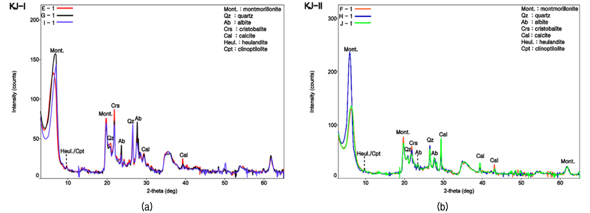
Table 1. Quantitative XRD analysis for mineral constituents of KJ-I and KJ-II powders (Yoon et al., 2018a)
2.2 Preparation of Compacted Bentonite
The dry density of the bentonite buffer is required to be greater than 1.6 g/cm3 based on the Korean design guideline and the buffer should be installed as compressed blocks produced by compressing bentonite buffer powder (Yoo et al., 2015). At first, the compacted bentonite was produced by floating die method (Kim et al., 2018) with bentonite powders, and a cold isostatic pressing (CIP) technique (Kim et al., 2018) was applied in order to form a homogenous sample. Thus, two cylindrical specimens with Gyeongju bentonite were prepared, which have 1.59 g/cm3 and 1.75 g/cm3 of dry densities with water contents (wc) of 10.6% and 8.7% for GJ-A and GJ-B, respectively, since the dry density of bentonite buffer is required to be greater than 1.6 g/cm3 based on the Korean design guideline (Yoo et al., 2015). The lower dry density (1.59 g/cm3) specimen has a preparation error with a slight insufficiency from the design guideline. The higher dry density (1.75 g/cm3) was based on a previous full-scale field test done for another separate project (Lee et al., 2019). Thus other dry density within these two limits can be properly interpolated for future usage. The water contents of the samples as shown in Table 2, were natural water contents preserved in initial process of collecting bentonite, because the EBS will be constructed with natural water content at the field. Thus the water contents were not controlled to simulate actual construction conditions. The dimensions of the specimens were 50 mm in diameter and 100 mm in length.
Table 2. Properties of compacted bentonite specimens
| Specimen ID | ρt (g/cm3) | ρd (g/cm3) | wc (%) |
| GJ-A | 1.76 | 1.59 | 10.6 |
| GJ-B | 1.9 | 1.75 | 8.7 |
2.3 Testing Setup and Equipment
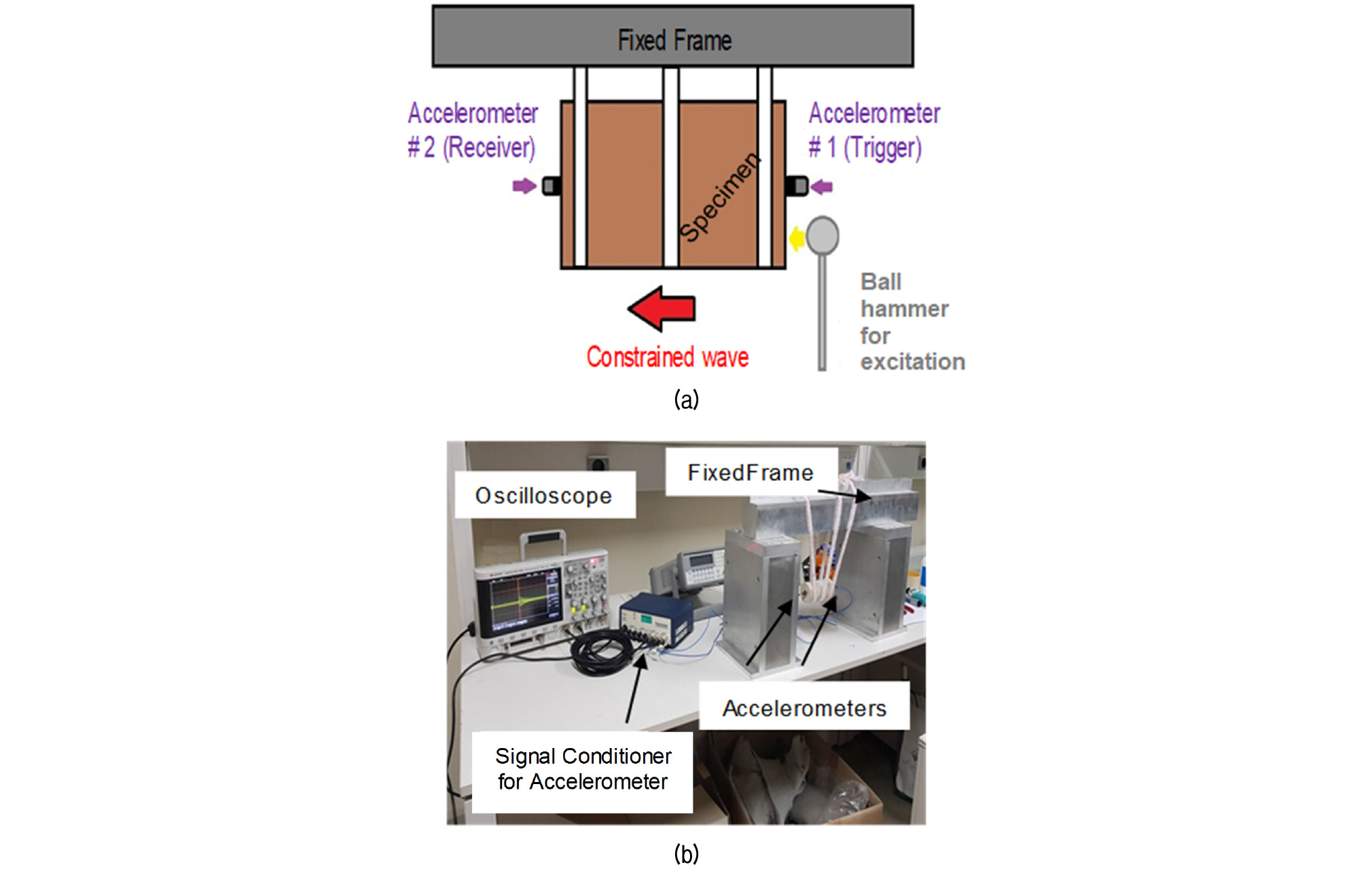
In this study, unconstrained compression wave velocity (Vc) and constrained wave velocity (Vp) of compacted bentonite specimens were measured using free-free resonant column tests (hereafter, FFRC tests). The FFRC testing setup in this study adopts a traditional manually excited free-free method (Pucci, 2010), by applying compression waves in the specimens suspended on a fixed frame. Compression waves were created by manually hitting a ball hammer on the surface of one end as illustrated in Fig. 3. The ball hammer consists of a steel ball and a rod, and in this study the 10-mm-diameter ball was used.
The FFRC testing setup performed in this study includes: (1) accelerometers (Acc#1 and Acc#2 in Fig. 3; PCB Piezotronics 353B16, 500g pk, 1 to 10 kHz) attached on the ends of the specimen, (2) four-channel sensor signal conditioner (PCB Piezotronics 482c), (3) four channel digital oscilloscope (Infinii Vision DSO-X 2004A), and (4) a computer code using MATLAB. In order to measure the velocities, the same testing setup presented in Fig. 3 was utilized but Vc and Vp were measured by different analysis methods: frequency response curves for Vc; and direct travel-time measurement for Vp (Pucci, 2010).
2.3.1 Unconstrained Compression Wave Velocity Vc, Young’s Modulus Emax and Material Damping Ratio Dmin
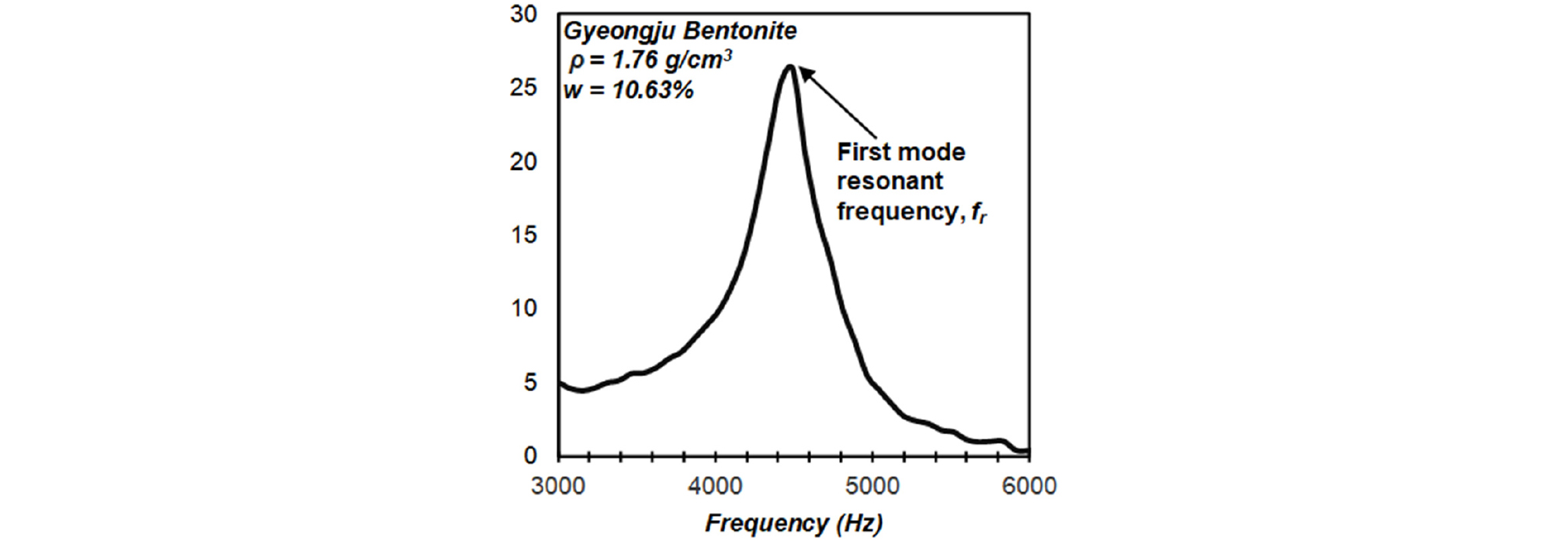
Unconstrained compression velocity (Vc), is evaluated by peaking a longitudinal resonant frequency of the specimen. A single accelerometer attached on the receiving end (Acc#2 in Fig. 3) is utilized. Once the longitudinal source is applied on the specimen, the response signal from the Acc#2 was recorded at the oscilloscope. Then, using MATLAB functions, the fast Fourier transform (FFT) analysis was performed to obtain a typical frequency response curve as shown in Fig. 4. The resonant frequency fr was determined from the frequency response curve and used to calculate unconstrained compression velocity, Vc.
Dynamic Young’s Modulus of Elasticity (Emax) can be determined using Eq. (1) from the fundamental longitudinal resonant frequency (fr), the length of the specimen (L) and specimen density (ρ). Dynamic Young’s modulus are rapid, nondestructive and provide small-strain linear elastic moduli.
| $$E_\max=\rho(2f_r\cdot L)^2$$ | (1) |
Traditional static methods require the measurement of axial strain as specimen is placed under unconfined axial stress. This fractures the specimen and hence requires multiple specimens if a relationship of the change of Young’s modulus with time is desired (Pucci, 2010). Under small-strain loading, the static and dynamic measured results are highly comparable for both Young’s modulus of elasticity Emax, and Poisson’s ratio ν (Bay and Stokoe, 1992; Pucci, 2010; Richart et al., 1970).
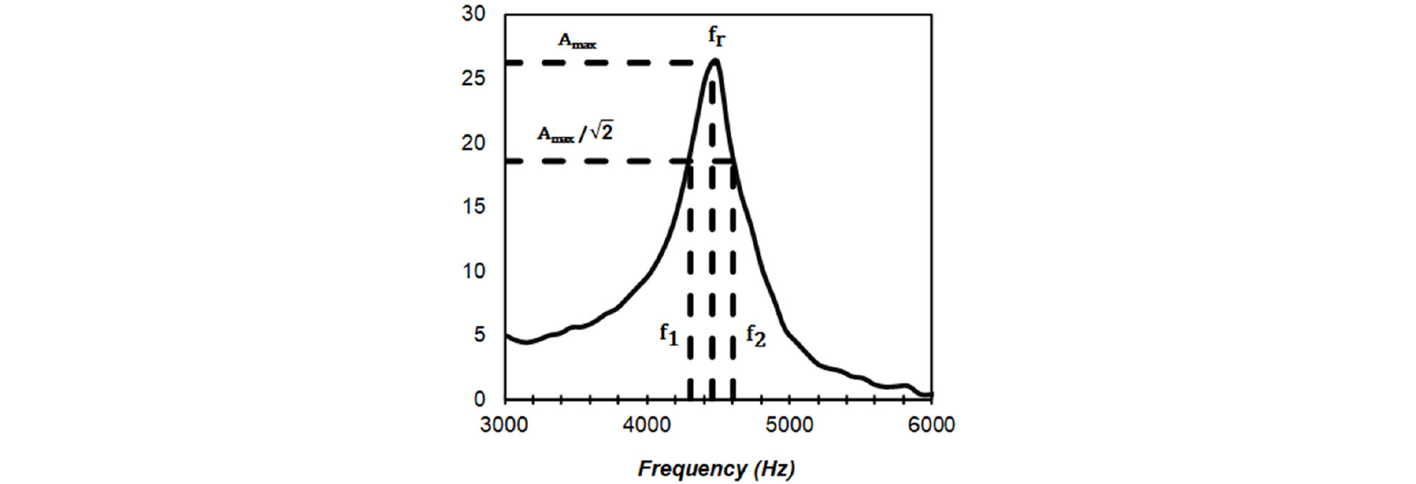
Material damping ratio (Dmin) is evaluated by the half-power bandwidth method using Eq. (2).
| $$D_\min=\frac{f_2-f_1}{2f_r}$$ | (2) |
where f1 and f2 are the half-power frequencies whose amplitude is equal to the peak resonant amplitude (Amax) divided by the (see Fig. 5). The purpose in evaluating the resonance curve is to determine the energy loss (material damping) of waves within a material (Pucci, 2010).
2.3.2 Constrained Compression Vp and Constrained Modulus Mmax
Constrained compression velocity (Vp) is evaluated using direct travel time method (Pucci, 2010; Ezersky, 2017). The specimen is longitudinally exited at one end of the specimen and two accelerometers are attached as shown in Fig. 3. One accelerometer (Acc#1 in Fig. 3) is for the trigger source of the excitation and the other (Acc#2 in Fig. 3) is for receiving the wave travelled through the specimen. The travel time of the wave (Δt) is directly determined by comparing the trigger signal and received signal as shown in Fig. 6. After evaluating Δt, the constrained compression wave velocity (Vp), and its corresponding constrained modulus (Mmax) were quantified.

2.3.3 Poisson’s Ratio
Using the relationship of the wave velocity Vp and Vc, Poisson ratio can be determined using Eq.3 (Richart et al., 1970).
3. Experimental Results and Discussion
3.1 Compressive Wave Velocity
Sources of varying weights and hardness have been used by trial and error to reduce noise in the response of all types of seismic tests (Pucci, 2010). Therefore, in this study, a 10-mm-diameter steel ball was used as a manual excitation source, since it produced repeatable and cleaner responses. As a result, Fig. 7 presents comparable frequency response curves of five trials for both GJ-A and GJ-B, respectively.
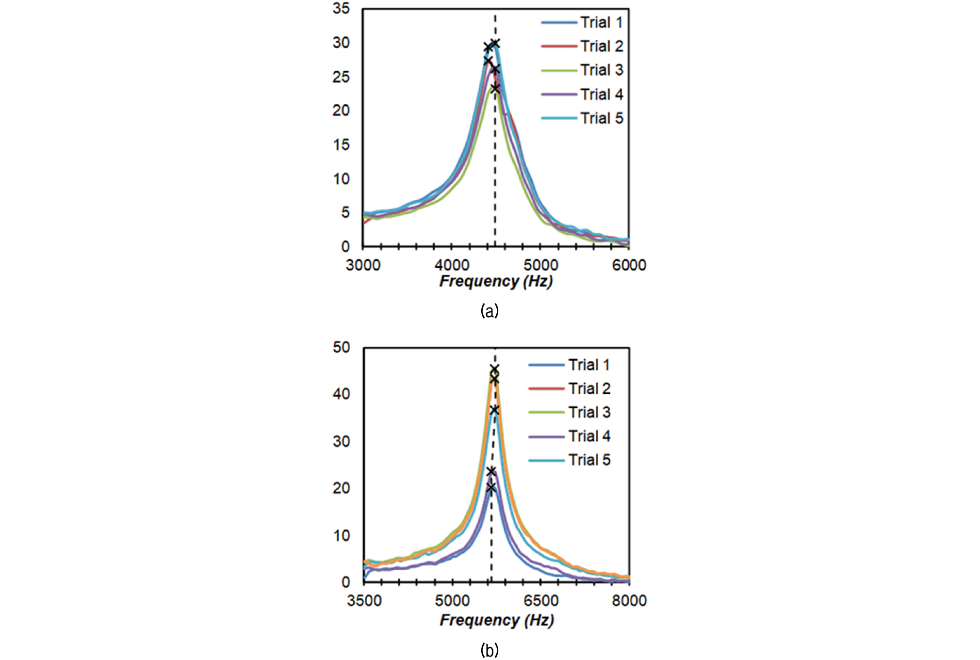
Fig. 8 compares Vp and Vc of GJ-A and GJ-B to those of Tisato and Marelli (2013). The Vp of GJ-B (= 1666.67 m/s) is significantly 33% higher than that of GJ-A (= 1,250.0 m/s), due to a higher dry density of GJ-B. Moreover, the Vp of GJ-A for ρd = 1.59 g/cm3 is 13.6% higher than the Vp of Tiasto and Marelli (2013) at wc = 10% and T = 30°C. Tisato and Marelli (2013)’s examined Spanish Bentonite which is the same material as described by Lloret et al. (2003), wherein Vp was measured for specimens with a dry density (ρd) of 1.66 g/cm3 and wc = 10% and 20% in the range of 30°C to 80°C. In the comparison of material matrix between KJ-II (present study) and Spanish bentonite (Tisato and Marelli, 2013), the feldspar and quartz constituents of KJ-II were higher than those of the Spanish bentonite; but the montmorillonite constituents are lower than that of the Spanish bentonite. It has been noted that with the increase in feldspar constituents in rocks, Vp increase, whereas the presence of mica decrease the compression wave velocity by Sharma et al. (2011).
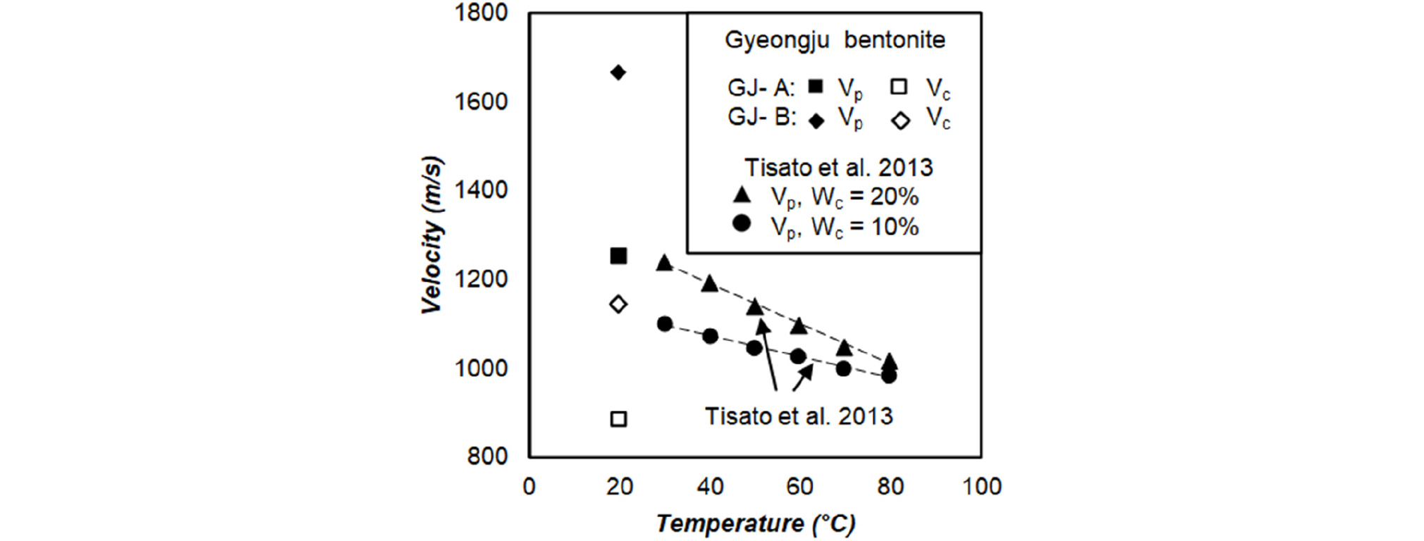
Fig. 8.
Velocity measurements, compared to Spanish Bentonite with minor sandy size filler constituents montmorillonite > 95 volume %, ρd = 1.66 g/cm3 ; Vp evaluation of Tisato and Marelli. (2013)
The unconstrained compression velocities Vc of GJ-A and GJ-B are lower than the Vp because of its wave characteristics. In general, the fastest stress wave in any geologic medium is the constrained compression wave Vp, which can be induced with a transient impulse parallel to the direction of wave propagation (Pucci, 2010).
3.2 Young’s Modulus Emax and Constrained Modulus Mmax
Fig. 9 and Table 3 compare the Emax and Mmax of GJ-A and GJ-B to Young’s modulus of Kunigel VI, MX-80 and KJ-I reported by Cho et al. (1999). All the results clearly present the increasing trend with the increase in dry density but GJ-A and GJ-B in this study are significantly higher than the other previous results. There was a difference of 95% between GJ-B (that is, KJ-II) and KJ-I (1.8 g/cm3) because they were tested by two different testing methods based on different strain ranges. The FFRC tests in this study measured moduli at small strain (less than 0.001%), on the other hand the previous results were done by unconfined compressive tests measuring modulus at intermediate to high strain range from 0.1% to 1%. The moduli at small strain generally present the maximum modulus (Kim and Choo, 2001; Pucci, 2010). On top of that, the high Vp measurements produce the higher value for Mmax than Emax.
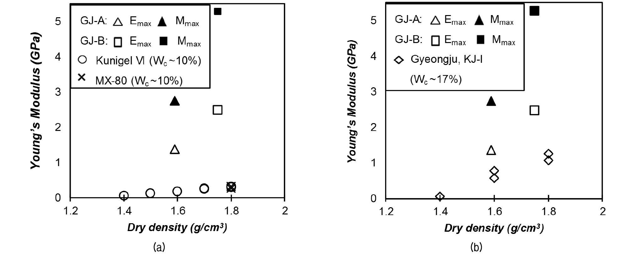
Table 3. Young’s modulus of compacted bentonite
| Compacted Bentonite | ρd (g/cm3) | wc % | E or Emax (GPa) | Testing Types | Ref |
| GJ-A (KJ-II) | 1.59 | 10.63 | 1.37 | FFRC | Present study |
| GJ-B (KJ-II) | 1.75 | 8.69 | 2.49 | FFRC | Present study |
| Kunigel VI | 1.4 | 10 | 0.066 | UC | Cho et al., 1999 |
| Kunigel VI | 1.5 | 10 | 0.121 | UC | Cho et al., 1999 |
| Kunigel VI | 1.6 | 10 | 0.179 | UC | Cho et al., 1999 |
| Kunigel VI | 1.7 | 10 | 0.257 | UC | Cho et al., 1999 |
| Kunigel VI | 1.7 | 10 | 0.264 | UC | Cho et al., 1999 |
| Kunigel VI | 1.8 | 10 | 0.315 | UC | Cho et al., 1999 |
| Kunigel VI | 1.8 | 10 | 0.307 | UC | Cho et al., 1999 |
| MX-80 | 1.8 | 10 | 0.321 | UC | Cho et al., 1999 |
| MX-80 | 1.8 | 10 | 0.269 | UC | Cho et al., 1999 |
| Gyeongju (KJ-I) | 1.4 | 17 | 0.059 | UC | Cho et al., 1999 |
| Gyeongju (KJ-I) | 1.6 | 17 | 0.784 | UC | Cho et al., 1999 |
| Gyeongju (KJ-I) | 1.6 | 17 | 0.588 | UC | Cho et al., 1999 |
| Gyeongju (KJ-I) | 1.8 | 17 | 1.079 | UC | Cho et al., 1999 |
| Gyeongju (KJ-I) | 1.8 | 17 | 1.275 | UC | Cho et al., 1999 |
3.3 Material Damping Ratio Dmin
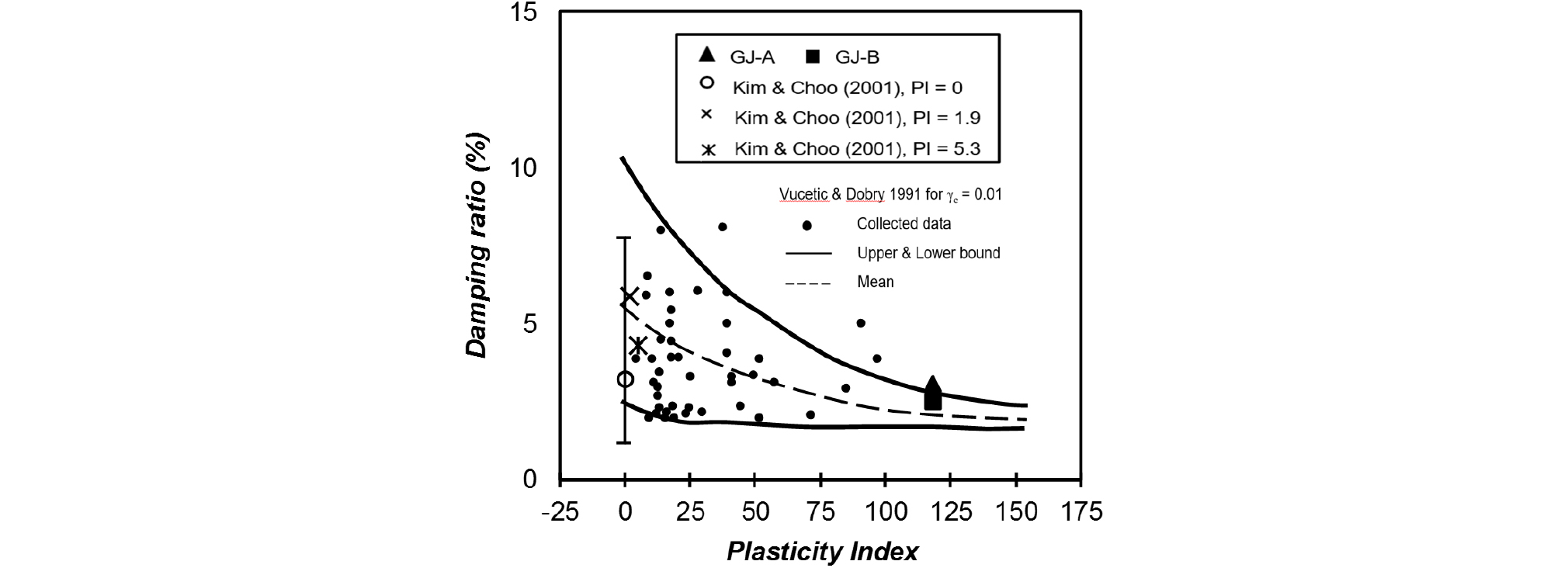
Fig. 10 compares the Dmin of Geongju compacted bentonite (GJ-A and GJ-B) to damping ratio at small shear strain (γc = 0.01%) collected from different laboratories by Vucetic and Dobry (1991) and Dmin of the Korean compacted residual soils of Kim and Choo (2001). It was found that the damping ratios of both KJ-II materials (GJ-A and GJ-B) correspond with the relationship between damping ratio and PI, which the damping ratio decreases with the increase in PI. The results of this study are located at the upper boundary of Vucetic and Dobry (1991). In addition, the Dmin of GJ-B is a little lower than that of GJ-A, indicating the denser compacted bentonite becomes more brittle. A significant decrease of 69% in Dmin of GJ-B compared with that of the compacted residual soils with PI = 5.3 from Kim and Choo (2001) was found; and also indicating that high plastic material property of GJ-B shows a decrease of 27%, compared with the mean Dmin of compacted residual soils from Kim and Choo (2001).
3.4 Poisson’s Ratio
Fig. 11 and Table 4 present the Poisson’s ratios of GJ-A and GJ-B were compared to the Poisson’s ratios measured by Cho et al. (1999) and Eloranta (2012). The Poisson’s ratios of GJ-A and GJ-B are comparable indicating negligible effect of dry densities; while those of KJ-1 (Cho et al., 1999) increases with the increase in dry density. However, the Poisson’s ratios of Cho et al. (1999) reaches a plateau in a range of 1.6 g/cm3 and 1.8 g/cm3 of dry densities. The Poisson’s ratio measured in this study using compressive wave velocities are higher than those of the previous results using unconfined compressive tests. In particular, Pucci (2010) reported that the Poisson’s ratio measured with the ratio of Vp/Vc is higher than the other methods with Vp/Vs and Vc/Vs (here, Vp = constrained compression velocity, Vc = unconstrained compression velocity, Vs = shear wave velocity). Moreover, this discrepancy increases with lower confining pressure. Eloranta (2012) performed one-dimensional and hydrostatic compression tests on purified MX-80 bentonite and reported that the Poisson’s ratio estimated from constrained modulus and bulk modulus ranges 0.42 to 0.5 at the dry density higher than 1.47 g/cm3. The Poisson’s ratio of this study is well agreed with the previous results of Eloranta (2012) and Pucci (2010), indicating the Poisson’s ratio’s measured in this study are relevant for the buffer material of EBS, which is supposed to be subjected to highly constrained boundary conditions.
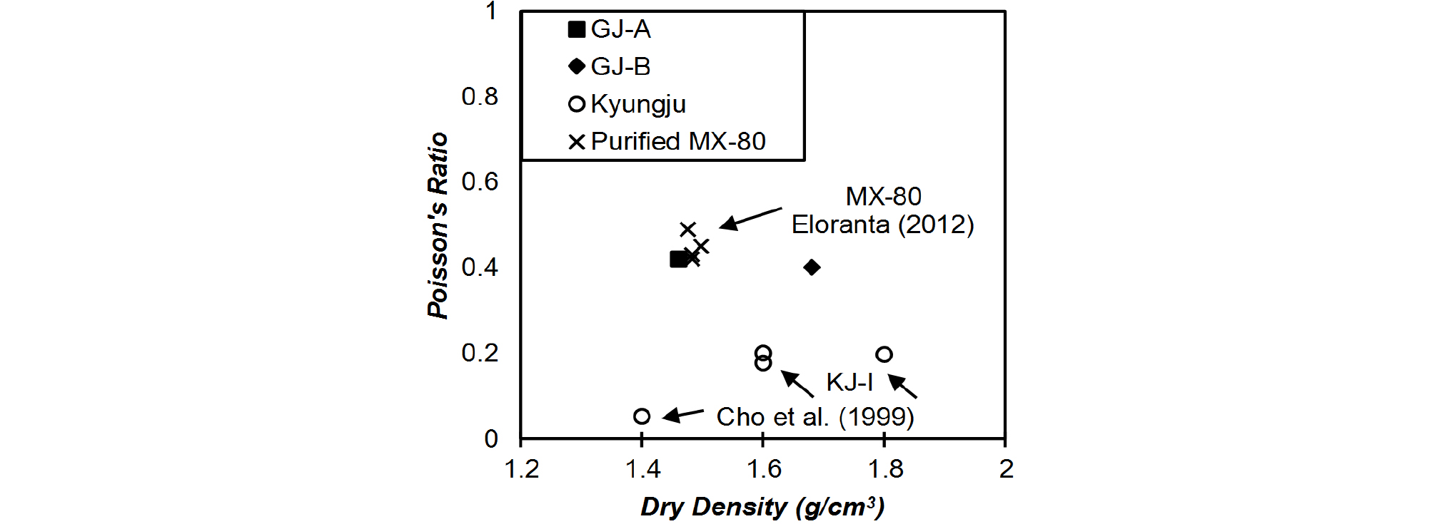
Table 4. Poisson’s ratio of compacted bentonite
| Compacted Bentonite | ρd (g/cm3) | wc % | Poisson's ratio | Types of Tests | Ref |
| GJ-A (KJ-II) | 1.59 | 10.63 | 0.42 | FFRC | Present study |
| GJ-B (KJ-II) | 1.75 | 8.69 | 0.40 | FFRC | Present Study |
| Gyeongju (KJ-I) | 1.40 | 17.00 | 0.05 | UC | Cho et al., 1999 |
| Gyeongju (KJ-I) | 1.60 | 17.00 | 0.18 | UC | Cho et al., 1999 |
| Gyeongju (KJ-I) | 1.60 | 17.00 | 0.2 | UC | Cho et al., 1999 |
| Gyeongju (KJ-I) | 1.80 | 17.00 | 0.2 | UC | Cho et al., 1999 |
| Purified MX-80 | 1.474 | 12.4 | 0.49 | ODCT & HCT | Eloranta, 2012 |
| Purified MX-80 | 1.482 | 7.6 | 0.42 | ODCT & HCT | Eloranta, 2012 |
| Purified MX-80 | 1.482 | 7.6 | 0.43 | ODCT & HCT | Eloranta, 2012 |
| Purified MX-80 | 1.497 | 7.6 | 0.45 | ODCT & HCT | Eloranta, 2012 |
* ODCT = One dimensional compression test ; HCT = Hydrostatic compression test
4. Conclusions
In this study, the seismic elastic mechanical properties of Gyeongju compacted bentonite (KJ-II) were evaluated using free-free resonant column tests. Two sets of compacted bentonite specimens were prepared having dry densities of 1.59 and 1.75 g/cm3 with water contents of 10.6% and 8.7%. Free-free resonant column tests were performed to measure constrained and unconstrained compression wave velocities. With the measured wave velocities, Young’s modulus (Emax) and constrained modulus (Mmax), material damping ratio (Dmin), and Poisson’s ratio at small strain were determined and summarized in Table 5.
Table 5. Summary of the compressive seismic velocities and moduli of this study
| Sample | Vc (m/s) | Vp (m/s) | Dmin | Emax (Gpa) | Mmax (Gpa) | Poisson's ratio |
| GJ-A | 883.00 | 1250.00 | 0.0306 | 1.37 | 2.75 | 0.42 |
| GJ-B | 1144.40 | 1666.67 | 0.0253 | 2.49 | 5.28 | 0.40 |
The Vp of GJ-A (KJ-II) is significantly higher than that of the Spanish bentonite measured by Tisato and Marelli (2013) due to its material matrix and room condition testing; and also the mineral constituents such as bentonite and feldspar, increase the rigidity of the specimen resulting to a stiffer material composite (Ismail and Shaari, 2010; Sarifuddin and Ismail, 2013). Thus Gyeongju bentonite has better mechanical characteristics to resist adverse and severe stresses applied on EBS than Spanish bentonite. For elastic moduli, a large difference between KJ-II of this study and KJ-I reported by Cho et al. (1999) was seen due to different testing methods and strain ranges. The study measures the Poisson’s ratio using the seismic method at small strain (<0.001%). On the other hand Cho et al. (1999) used unconfined compressive tests usually tested at high strain range (0.1% to 1%). The present findings confirm that the Dmin of KJ-II materials were located at the upper boundary of Vucetic and Dobry (1991), following the relationship of damping ratio and PI. In addition, the results for the Poisson’s ratio of (KJ-II) are almost constant in the range of 1.59 to 1.75 g/cm3 of dry densities. On top of that, the Poisson’s ratio of this study (KJ-II) are higher than those of KJ-I tested by Cho et al. (1999) because of different testing methods and strain ranges, which is the same reason for the elastic modulus.
This study provides the first observation on dynamic elastic property of the Gyeongju compacted bentonite. The dynamic and static elastic parameters are correlated with each other, so that the results of this study will be a basis to understand the mechanical characteristics of Gyeongju compacted bentonite. However, the dynamic property may not be thoroughly representative of mechanical property. In view of this, further comparative studies between static and dynamic moduli on Gyeongju bentonite are underway. It is intended to present these test results to provide further insights on this issue in the future.
