

1. Introduction
2. Derivation of an arching formula to consider various 3D conditions
3. Validation of the expanded formula
4. Analysis of the effects of various conditions and comparison of the results
5. Conclusions
1. Introduction
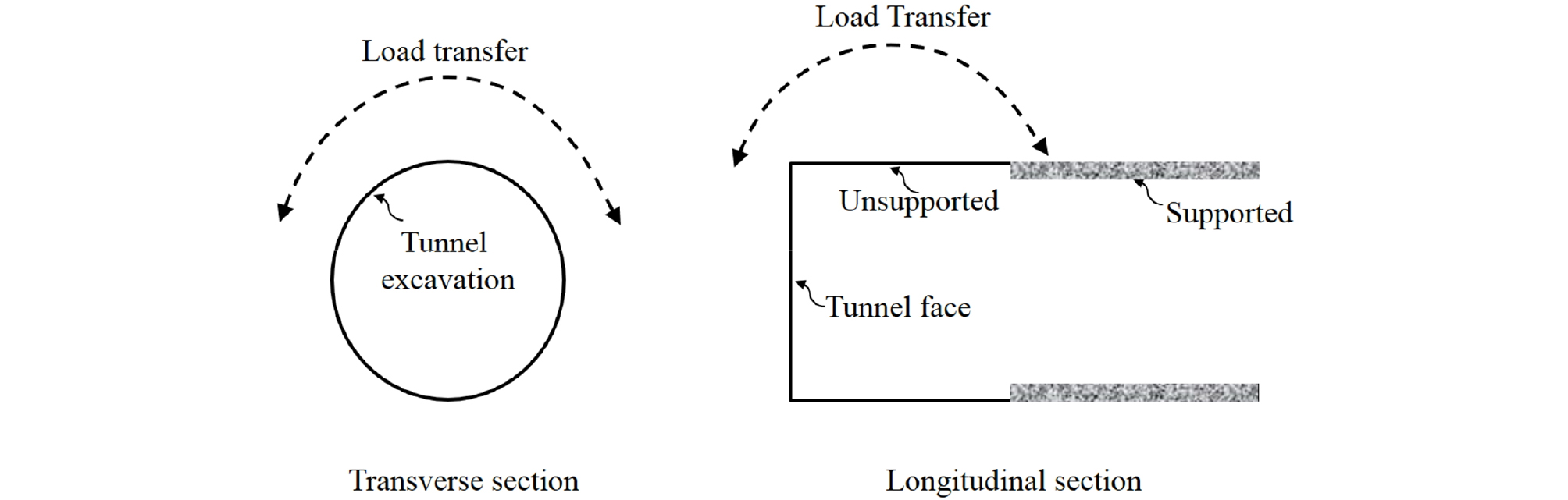
Soil adjoining a yielded part is displaced relative to adjacent soil that is undergoing slight displacement. The relative displacement is subject to shear resistance from the surface that is in contact with the adjacent soil, which transfers load from the yielded part to the adjacent parts. Thus, the load on the yielded part decreases while the load on the adjacent parts increases. The result of this mechanism is called the arching effect, which is typically observed in the displacement of the crown of a tunnel. Understanding this arching phenomenon is very important for understanding load behaviors and designing tunnel supports.
Many studies on arching have been carried out, including early efforts by Engesser (1882), Bierbaumer (1913), Cain (1916), Marston (1930), Caquot (1934), and Völlmy (1937). Terzaghi (1943) was the first to systematically study the arching mechanism using trapdoor tests. Since then, many studies have been conducted, including theoretical studies (Nielson, 1966; Getzler et al., 1970; Spangler and Handy, 1982; Adachi et al., 1999; Li et al., 2005; Pirapakaran and Sivakugan, 2007; Singh et al., 2011; Li et al., 2013; Son, 2017), experimental studies (McNulty, 1965; Ladanyi and Hoyaux, 1969; Vardoulakis et al., 1981; Evans, 1983; Ono and Yamaha, 1990; Paikowsky et al., 1993; Paikowsky and Hsienjen, 2002; Santichaianaint, 2002; Adachi et al., 2003; Vorster, 2005; Chau and Bolton, 2006; Costa et al., 2009; Sardrekarimi and Abbasnejad, 2010; Lee and Lee, 2010; Chevalier et al., 2012; Ahmadi and Hosseininia, 2013; Iglesia et al., 2014; Pardo and Sáez, 2014; Yim and Lee, 2017), and numerical studies (Koutsabeloulis and Griffiths, 1989; Sakaguchi and Ozaki, 1992; Pirapakaran and Sivakugan, 2007; Nunes and Meguid, 2009; Chevalier and Otani, 2010; Chen et al., 2011; Pardo and Sáez, 2014; Sivakugan et al., 2014; Falaknaz et al., 2015).
Some experimental and numerical studies have been performed under 3D conditions. However, most theoretical studies on the arching mechanism using trapdoor tests considered 2D plane strain conditions and assumed that the sliding surface on top of the trapdoor is vertical, which may not be the case in actual field conditions. The sliding surface on a trapdoor could be inclined in actual conditions, which has been observed in experimental tests (Völlmy, 1937; Costa et al., 2009) and numerical tests (Pardo and Sáez, 2014). There has been some effort to reflect 3D conditions with a vertical sliding surface (Adachi et al., 1999; Li et al., 2005; Pirapakaran and Sivakugan, 2007) and 2D conditions with an inclined sliding surface for backfilled trenches or stopes (Singh et al., 2011; Li et al., 2013). However, it is still difficult to find a study that has presented a full 3D expansion with inclined sliding surfaces for trapdoor problems and examined its effects on the change in vertical stress. A recent study expanded the 2D Terzaghi arching formula to a 3D formula that considers inclined sliding surfaces in the transverse direction under 3D tunnel excavation conditions (Son, 2017). The findings indicated that there is a big difference between the 2D and 3D results in the vertical stresses induced for various tunnel excavation and ground property conditions.
This study further expands the previous 3D arching formula, considering the effects of ground properties and inclined sliding conditions in both the transverse and longitudinal directions considering anisotropic ground conditions, as well as various 3D tunnel excavation conditions. The arching formula for 3D conditions was validated by both an analytical method and comparison with experimental test results from Adachi et al. (2003). The formula was used to examine the changes in vertical stress for various ground properties, inclined sliding, excavation, and surcharge pressure conditions. The results were compared with those of the 2D Terzaghi formula. The findings could provide better understanding of the complex arching phenomena in tunnel construction.
2. Derivation of an arching formula to consider various 3D conditions
Terzaghi (1943) developed an arching formula that considers the force equilibrium of the differential area between two vertical surfaces, as shown in Fig. 1.
| $$\therefore\sigma_v=\frac{B\cdot\gamma-c}{K\cdot\tan\phi}(1-e^{-K\tan\phi\frac zB})+qe^{-K\tan\phi\frac zB}$$ | (1) |

For z=∞ and surcharge pressure q=0 on the ground surface,
| $$\sigma_v=\frac{B\cdot\gamma-c}{K\cdot\tan\phi}$$ | (2) |
where 2B is the width of yielding strip, γ is the unit weight, c is the cohesion, is the friction angle, and K is the earth pressure coefficient. However, Terzaghi formula is limited to 2D vertical sliding surface conditions and therefore it is difficult to apply the formula to 3D tunnel excavation and inclined sliding surface conditions.
The proposed 3D arching formula in this study considers the effects of ground properties and inclined sliding conditions in both the transverse and longitudinal directions as well as 3D tunnel excavation conditions (Fig. 2). A sliding surface does not generally form a consistent sliding angle from the part of deflection to the ground surface, and the inclined sliding angle can differ for various orientations. Despite the new considerations, it is still assumed that the inclined sliding angle is consistent, regardless of the depth and orientation of the sliding surface. An arching theory that considers the effects of depth and orientation of the sliding angle could be developed by considering a function that reflects the influences of depth and orientation (Son, 2017). However, it would be very complicated and require a numerical method, so it is left for future work.
The arching formula for 3D conditions was derived using Terzaghi’s assumptions of homogeneous, isotropic, and semi-infinite soil. As shown in Fig. 3, the force equilibrium in the differential zone between the sliding surfaces with the angles of α1 and α2 was considered to incorporate the inclined sliding surfaces in 3D tunnel excavation conditions. Eq. (5) can be used to assess the vertical stress in various 3D ground and excavation conditions with inclined sliding surfaces in both the transverse and longitudinal directions. The equation is obtained by considering the force equilibrium (eq. (3)) of the differential zone in the depth direction (z) and the stress transformation (eq. (4)), followed by rearranging, integrating, and solving for the stress. No infinitesimal values such as dz2 were considered to derive the expanded formula.

where
,
In the longitudinal and transverse directions, c1 and c2 are the cohesion, 1 and 2 are the friction angles, K1 and K2 are the earth pressure coefficients, and α1 and α2 are the inclination angles of the sliding surface, respectively (Fig. 3).
3. Validation of the expanded formula
The expanded formula was validated in different ways. The analytical validation of the formula was performed as follows:
Validation 1:
If z=0, α1=α2=90°, L=∞, K1=K2=K, c1=c2=c, and 1 and 1=1 and 2=1 and , , o.k
Validation 2:
If z=H=∞ with all other conditions the same as in Validation 1,
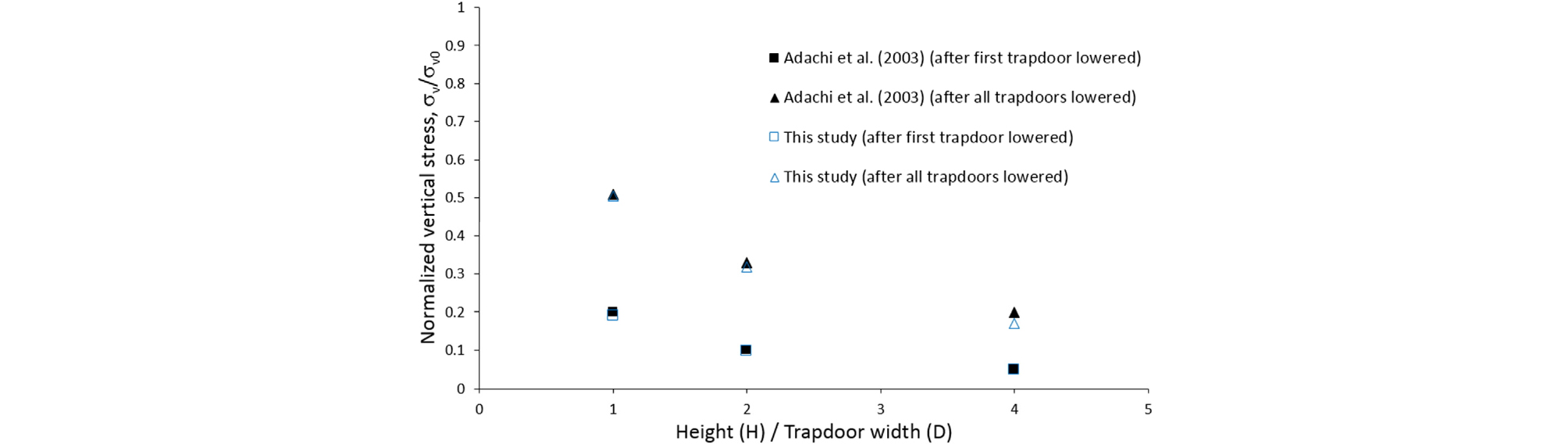
The expanded arching formula was also validated by comparison with 3D experimental test results (Adachi et al., 2003). The experimental tests were carried out through three-dimensional trapdoor tests with a vertical sliding surface and constant width. The change in the vertical stress on the trapdoors was examined by varying the ratio of the overburden height (H) to the trapdoor width (D) and lowering the six trapdoors arranged in the longitudinal direction one after another. The vertical stress (σv) measured on the first trapdoor for different H/D ratios and different stages was reported in terms of the normalized stress with respect to the initial vertical stress (σvo). The experimental results were compared with those from the derived formula for the same conditions (Fig. 4). The comparison shows quite similar results and trends, which further validates the derived formula. Both the analytical and experimental validations of the expanded formula justify its use for extended parametric studies of various conditions.
4. Analysis of the effects of various conditions and comparison of the results
The expanded 3D arching formula was used for parametric studies under various inclination angles (α1, α2) of the sliding surface, excavation widths and lengths, ground properties condition, and surcharge pressure conditions. The change of the vertical stress was examined under different conditions, and the results were compared with those of Terzaghi. Fig. 5 compares the vertical stresses induced with different excavation widths (2B). In the Terzaghi formula, the longitudinal excavation length is always infinite. the vertical stress increased gradually as the excavation width and length increased for the same inclination angle. However, the vertical stress decreased as the inclination angle decreased. The effect of the inclination angle became more prominent with increased excavation width.
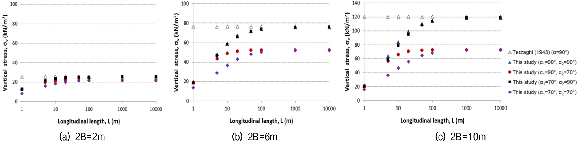
As the angle (α2) in the transverse direction decreased, the effect of the inclination angle (α1) in the longitudinal direction again increased, but it decreased as the excavation length increased. When L exceeded about 100 m, the change in vertical stress became small, regardless of the inclination angle. The model test by Adachi el al. (2003) showed similar results and trends. The results indicate that the vertical stress is significantly affected by both the excavation width and length as well as the inclination angle of the sliding surface.
Fig. 6 compares the vertical stresses induced with different excavation depths (H) and longitudinal excavation lengths (2L) under an excavation width (2B) of 6 m. The vertical stress for the same inclination angle increased gradually as the excavation depth and length increased, but the stress change decreased as the excavation depth increased. The effect of the inclination angle became more prominent with shallow excavation depth. As the transverse angle α2 decreased, the effect of the longitudinal inclination angle α1 increased, but the effect decreased as the excavation length increased.
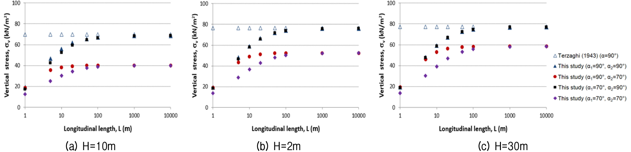
Fig. 7 compares the vertical stress results for different cohesion (c1 and c2) and longitudinal excavation length (2L) for the case of Fig. 5b. As the cohesion increased, the vertical stress decreased, but the stress increased with the excavation length. The vertical stress was more affected by the cohesion in the transverse direction and a low excavation length. Furthermore, the vertical stress could be less than 0 at a high cohesion and low excavation length, which implies that there is no vertical stress. The effect of the longitudinal inclination angle α1 increased as the transverse angle α2 decreased, but the effect decreased as the excavation length increased.
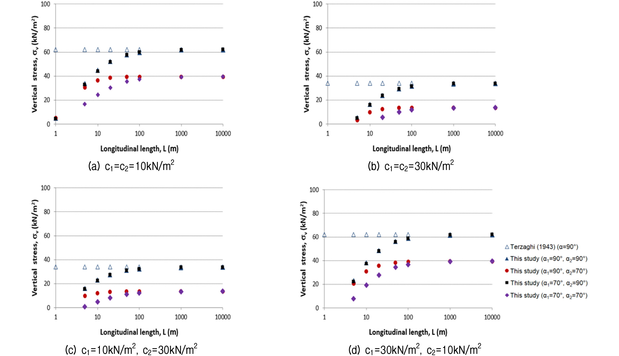
Fig. 8 compares the results for different friction angles (1 and 2) and longitudinal excavation lengths (2L) for the case of Fig. 5b. The induced vertical stress and the effect of the inclination angle decreased with increasing friction angle. As observed in the cohesion results, the vertical stress was more affected by the friction angle in the transverse direction and at a low excavation length. The effect of the longitudinal inclination angle α1 was similar to that in the case of cohesion. The results indicate that the vertical stress in a trapdoor problem is interactively affected by the combination of the excavation, sliding, and ground properties conditions.
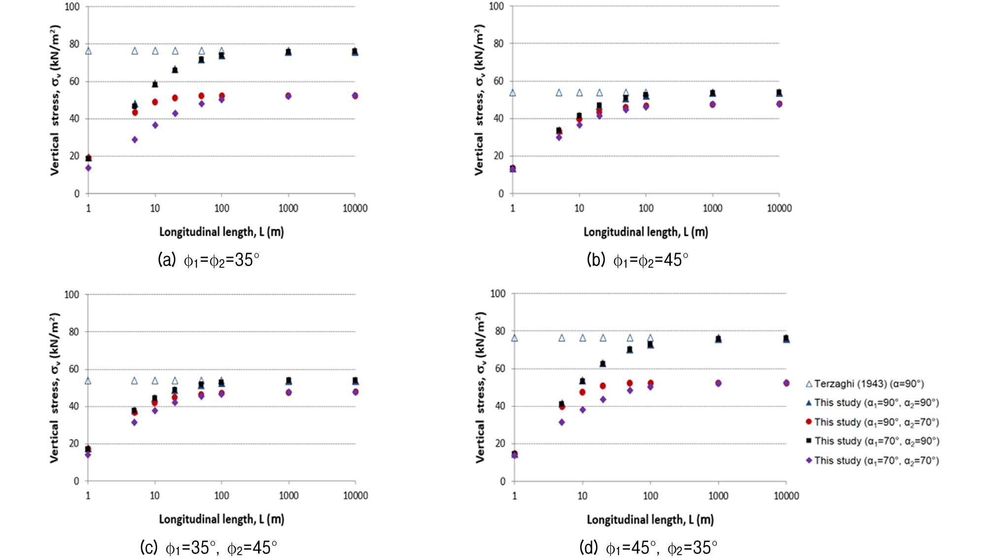
Fig. 9 compares the vertical stresses induced with different values of the earth pressure coefficient (K) and longitudinal excavation length (2L) for the case of Fig. 5b. When K2 was increased to 2, the vertical stress decreased significantly, and the effect was bigger for the longer longitudinal excavation length and the higher inclination angle. As K1 was increased to 2, the vertical stress decreased at low excavation length, but the stress did not change much when K1 was increased to 2 compared to K1=K2=1 with L of 100 m or more. These results indicate that the earth pressure coefficient of the ground directly affects the maximum shear strength induced on the sliding surface interacting with both excavation and sliding conditions.
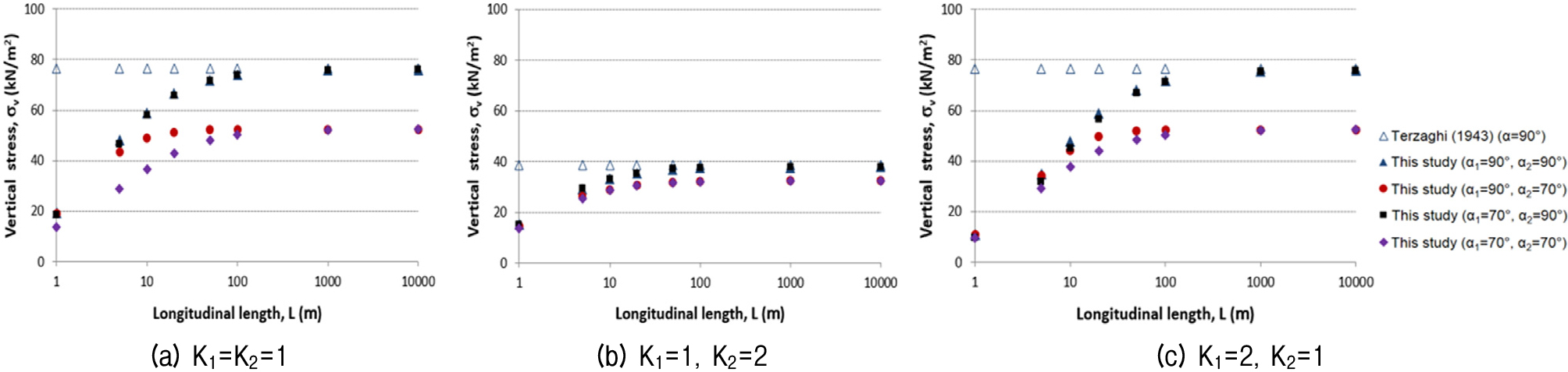
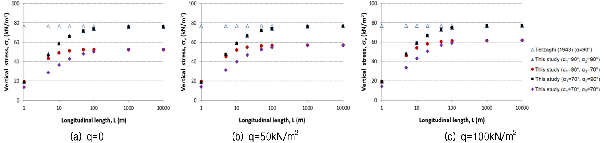
Fig. 10 compares the results for different ground surcharge pressures (q) and longitudinal excavation lengths (2L) for the case of Fig. 5b. The vertical stress increased as the ground surcharge pressure increased, and the effect was more prominent at low inclination angle and excavation length. The effects of the excavation length and inclination angle decreased as the ground surcharge pressure increased. As the excavation length increased, the effect of the inclination angle (α1) in the longitudinal direction decreased.
5. Conclusions
The following conclusions were drawn from this study:
(1) The study further expanded a previous 3D arching formula by considering the effects of ground properties and inclined sliding conditions in both the transverse and longitudinal directions considering anisotropic ground conditions, as well as 3D tunnel excavation conditions. The expanded formula was validated by both an analytical method and comparison with experimental test results.
(2) Extended parametric studies were conducted with the expanded formula to examine the changes in vertical stress for various ground properties, inclined sliding, excavation, and surcharge pressure conditions. The results indicated that vertical stress can be significantly affected by the combination of the excavation, sliding, ground properties, and surcharge conditions.
(3) The vertical stress increased as the excavation width and length increased, the inclination angle increased, the cohesion and friction angle decreased, the earth pressure coefficient decreased, and the surcharge pressure increased. Under the conditions examined, the stress was more affected at low excavation lengths and by the ground properties in the transverse direction.
(4) The expanded formula could more realistically represent arching phenomena that occur in the field, where inclined sliding surfaces can form, definite longitudinal excavation lengths form during excavation process, and different ground properties can occur in different directions due to either natural deposits or ground improvements. The results from this study could provide useful information for investigating practical arching effects in the field, as well as improve the understanding of various arching phenomena.
List of symbols
σv : Vertical stress
σn1 : Normal stress on the sliding surface in the longitudinal direction
τn1 : Shear stress on the sliding surface in the longitudinal direction
σn2 : Normal stress on the sliding surface in the transverse direction
τn2 : Shear stress on the sliding surface in the longitudinal direction
2B : Width of yielding strip in the transverse direction (width of excavation)
2L : Length of yielding strip in the longitudinal direction (length of excavation)
H : Depth of yielding strip (depth of excavation)
z : Arbitrary depth
α1 : Inclination angle of sliding surface in the longitudinal direction
α2 : Inclination angle of sliding surface in the transverse direction
γ : Soil unit weight
1 : Soil friction angle in the longitudinal direction
2 : Soil friction angle in the transverse direction
c1 : Soil cohesion in the longitudinal direction
c2 : Soil cohesion in the transverse direction
K1 : Earth pressure coefficient in the longitudinal direction
K2 : Earth pressure coefficient in the transverse direction
q : Surcharge pressure on the ground surface
